skip to main |
skip to sidebar
Distort
These tools allow you to distort the area under your brush. Click twice on the tool to choose from among the various types of distortion effects. These tools are only available in the ImageForge PRO version. Simply double-click on the tool to select from the available tools.

You can use the Update Drawing Area icon to control whether each stroke of the tool builds upon the last stroke, or if it is applied to the original image as it was when you began using the tool. Example: if you wished to smear an area, and then smear the already smeared area, you would enable the Update Drawing Area option. If you did not want to smear the area further with each stroke, you would not enable Update Drawing Area.
Rotate tool
This tool is used to rotate the active layer, a selection or a path. When you click on the image or the selection with this tool a Rotation Information dialog is opened. There, you can set the rotation axis, marked with a point, and the rotation angle. You can do the same by dragging the mouse pointer on the image or the rotation point.
4.5.2. Activate the Tool
· You can can access the Rotate tool from the image-menu through: Tools → Transform Tools → Rotate,
· or by clicking the tool icon: in the Toolbox.
· or by using the Shift+R key combination.
- Scale Tool
Use the Scale Tool to resize and stretch portions of geometry relative to other entities in your model. Activate the Scale Tool from the Tool Palette or the Tools menu.
Keyboard Shortcut:S
Note - A Global Scale is an operation whereby the entire model is scaled simultaneously by applying a desired dimension to the distance between two points. The Scale Tool is only intended to perform scaling operations on portions of your model (not the entire model). Use the Tape Measure Tool's Global Re-Scale functionality to perform global scaling operations.
Scaling Geometry
Select the Scale Tool. The cursor will change to a box within another box.
Click on the entity. Scaling grips will appear around the selected geometry.
Click on a scaling grip. The selected grip and the opposite scaling grip will highlight in red. Each scaling grip provides a different scaling operation. See Scaling Options section for further information.
Move the cursor to scale the entity. The Value Control Box (VCB) displays relative size of the item as you scale the item. You can enter the desired scale dimensions after the scale operation is complete.
Note - Press the Esc key at any point during the operation to start over.
Click to finish scale operation.
The Zoom Tool allows you to zoom in on an area for detailed editing. Remember though, it is just a magnified version of your image, it is not an enlarged version. If you save the image in it's zoomed state it will not save large, it will save in it's original size. To enlarge the image you must Resize it.
Pan Tool
Use the Pan Tool to move the camera (your view) vertically and horizontally. Activate the Pan Tool from either the Tool Palette or the Camera menu.
Keyboard Shortcut: H
Panning the View
The Pan Tool performs a pan operation. To pan using the Pan Tool:
Select the Pan Tool. The cursor changes to a hand.
Click anywhere in the drawing area.
Move the cursor in any direction to pan.
Panning While in the Orbit Tool (3-Button Mouse)
Press and hold the Shift key while in the Orbit Tool to temporarily activate the Pan Tool. Or, press and hold the left mouse button while pressing and holding the middle mouse button (scroll wheel) to activate the Pan Tool.
Panning While in Other Tools (1-Button Mouse)
Click and hold the Control, Command, and Shift keys simultaneously while clicking and holding the left mouse button to temporarily activate the Pan Tool (if you have only one mouse button).
Auto Shapes
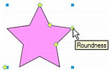
Auto Shapes are intelligent vector object groups that adhere to specialized rules to simplify the creation and editing of common visual elements. Auto Shape tools draw object groups. Unlike other object groups, selected Auto Shapes have diamond-shaped control points in addition to the object group handles. Each control point is associated with a particular visual property of the shape. Dragging a control point alters only the associated visual property. Most Auto Shape control points have tooltips that describe how they affect the Auto Shape. Move the pointer over a control point to see a tooltip that describes the property governed by that control point.
Auto Shape tools create shapes in preset orientations. For example, the Arrow tool draws arrows horizontally. You can transform Auto Shapes to change their orientation. For more information, see Transforming and distorting selected objects and selections.
Although each Auto Shape tool in the Tools panel uses the same easy drawing method, the editable attributes for each Auto Shape are different.
Arrow draws object groups that appear as simple arrows of any proportions. Using control points, you can adjust the arrowhead flare, the tail length and width, and the tip length.
Beveled Rectangle draws object groups that appear as rectangles with beveled corners. Using control points, you can edit the amount of bevel for all corners together, or change the bevel of individual corners.
Chamfer Rectangle draws object groups that appear as rectangles with chamfers, corners that are rounded to the inside of the rectangle. You can edit the chamfer radius of all corners together, or change the chamfer radius of individual corners.
Connector Line draws object groups that appear as three-segment connector lines, such as those used to connect the elements of a flowchart or organizational chart. Using control points, you can edit the end points for the first and third sections of the connector line, as well as the location of the second section, which connects the first and last sections.
Doughnut draws object groups that appear as filled rings. Using control points, you can adjust the inner perimeter or split the shape into pieces.
L-Shape draws object groups that appear as right-angled corner shapes. Using control points, you can edit the length and width of the horizontal and vertical sections, as well as the curvature of the corner.
Pie draws object groups that appear as pie charts. Using control points, you can split the shape into pieces.
Smart Polygon draws object groups that appear as equilateral polygons with 3 to 25 sides. Using control points, you can resize and rotate, add or remove segments, increase or decrease the number of sides, or add an inner polygon to the shape.
Rounded Rectangle draws object groups that appear as rectangles with rounded corners. Using control points, you can edit the roundness of all corners together, or change the roundness of individual corners.
Spiral draws object groups that appear as open spirals. Using control points, you can edit the number of spiral rotations, and you can determine whether the spiral is open or closed.
Star draws object groups that appear as stars with any number of points from 3 to 25. Using control points, you can add or remove points, and you can adjust the inner and outer angles of the points.
Add Shadow adds a shadow beneath the selected object based on the dimensions of that object. The shadow is actually an Auto Shape and, like all Auto Shapes, contains control points that you can use to manipulate its appearance. For example, you can Shift-drag the Direction control point to constrain its movement to a 45-degree angle. Clicking the Direction control point resets the shadow to the original shape.
Rectangle Tool
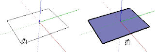
Use the Rectangle Tool to draw rectangular Face entities, specified by clicking at two opposite corners of the desired shape. Activate the Rectangle Tool from either the Tool Palette or the Draw menu.
Keyboard Shortcut: R
Drawing a Rectangle
Rectangles can be placed on e xisting faces or separate from existing geometry (aligned to an axes plane). To draw a rectangle:
Select the Rectangle Tool. The cursor changes to a pencil with a rectangle.
Click to set the first corner point of the rectangle.
Move the cursor diagonally.
Note - Press the Esc key at any point during the operation to start over.
Click again to set the second corner point of the rectangle.
Drawing a Square
Squares are created with the rectangle tool in conjunction with the Square help tag. To draw a Square:
Select the Rectangle Tool and Click once on the first corner point.
Move your mouse to the opposite corner. A diagonal dotted line will appear, along with a Square help tag, when you are in a position that will create a square.
Note - Press the Esc key at any point during the operation to start over.
Click to finish.
Tip - A dotted line and Golden Section help tag appears when you are in a position to create a Golden Section.
Alternately, you can press your mouse button on the first corner of your rectangle, drag to the opposite corner, and release the mouse button.
Tip - Use the Axes tool to re-align the axes, prior to drawing your rectangle, if you want to draw a rectangle that is not aligned with the default drawing axes orientation.
Specifying Precise Rectangle Values
A rectangle's dimensions dynamically appear in the VCB as you draw. Specify exact length and width dimensions by typing them in the VCB, and pressing Enter or Return, either after the first corner is clicked or immediately after the rectangle is drawn.
SketchUp will use the current document units setting if you only type in a numerical value. You can also specify either Imperial (such as 1’6”) or Metric (such as 3.652m) units at any time, regardless the document units setting.
You can also type one dimension at a time in the VCB. If you enter a value and a comma (3',), the new value will be applied to the first dimension, and the second dimension will be retained from before. Similarly, if you type a comma and then a value (,3'), only the second dimension will be changed.
Tip - If you enter a negative value (-24, -24), SketchUp will apply that value in a direction opposite to the one you indicated while drawing and accept any new values in the new direction.
Drawing Rectangles by Inference
The Rectangle Tool uses SketchUp's geometric inference engine to help you place your rectangles in 3D space. The inference decisions, made by the inference engine, are displayed in the drawing area as inference lines and inference points. These lines and points show precise alignment between the rectangle you are drawing and the geometry of your model.
For example, if you move your mouse over an endpoint of an existing edge and then move away in the direction of an axis, a dotted inference line with a From Point help tag will appear.
This help tag indicates that you are aligned to that end point. You can also use a From Point inference to draw rectangles vertically or at non-orthogonal planes.
Locking a Rectangle to the Current Inference Direction
Press and hold the Shift key, while the rectangle you are drawing is the specific color of an axis, to lock drawing operation to that axis.


